Assembling a Mainstream Intel Gaming PC (2017)
Introduction
 Here at The Tech Buyer’s Guru, it’s our goal to make building a PC easier for everyone, from first-time builders to veterans. Whether you’re a serious gamer looking to build the all-conquering gaming rig, a professional needing an affordable but powerful PC to use while working from home, or a parent looking to share a great hobby with a child, there’s so much to gain by putting together your own PC.
We’ve been publishing hands-on, step-by-step PC building guides since 2013, and they’ve proven to be very popular with our readers. But time doesn’t stand still, and neither does PC technology. Every year we see new products released, indeed entirely new categories of products created. Just a few years ago, hard drives still dominated the storage market, modular ultra-efficient power supplies came at very high prices, and PC cases were constrained by bulky drive cage arrays and loud 120mm fans that produced little actual airflow. Well, all that has changed, and what we’re going to be showing you in this guide is a truly modern PC, fit for the year 2017. We spend a lot of time (and money!) putting together these guides every year because we strongly believe that PC builder’s guides must change with the times. Could we keep sending you to the same old guide we published years ago, similar to ones you’ll find on other sites? Sure, but then we’d be doing you a disservice, because what you really need to know is how to build a PC today, not how you would have built a PC using obsolete components.
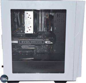
And as always, in putting together this guide, it was important to us to build a PC that we actually wanted ourselves. So we chose the incredibly-stylish and incredibly-affordable SilverStone RL06-Pro. Special thanks to SilverStone for letting us get a crack at this case before it even hit the market. We’ve published a full review of the case, and we’re pretty sure a lot of our readers are going to agree that this case is a must-have item. To make sure we can give you the best advice regarding the latest trends in overclocking and motherboard connectivity, we of course had to build this system using Intel’s new Kaby Lake platform. Special thanks to MSI for providing its cutting-edge Z270 Gaming Pro Carbon motherboard to get us up to speed on what a serious Z270 board can do. As for the CPU, as always we bought it at retail (in this case, the $350 Core i7-7700K), because we firmly believe that requesting media samples of performance-related items like CPUs and GPUs limits journalistic freedom and potentially taints the entire evaluation. We don’t want no cherry-picked gear!
With that being said, here’s the full parts list for this build:
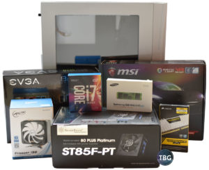
- CPU: Intel Core i7-7700K
- Motherboard: MSI Z270 Gaming Pro Carbon (thank you to MSI for providing this review sample)
- Video Card: EVGA GeForce GTX 1070 SC 8GB
- SSD #1: Samsung 850 Evo 500GB M.2
- SSD #2: Crucial MX300 1TB 2.5″
- RAM: Corsair Vengeance 2x8GB DDR4-3000
- Case: SilverStone RL06-Pro (thank you to SilverStone for providing this review sample)
- CPU Cooler: Arctic Freezer i32 (thank you to Arctic for providing this review sample)
- Power Supply: SilverStone Strider 850W Platinum (thank you to SilverStone for providing this review sample)
- Operating System: Windows 10 Flash Drive
All told, the retail value of these components was just over $1,800 at the time of publication. As built, this system is most similar to the configuration listed in our $1,500 High-End Gaming PC Buyer’s Guide at the time of publication, but with upgraded SSDs. Note that in some ways, this build straddles the line between mid-range and ultra-high-end, and we chose these parts to provide a broader view of the components available on the market today. If you’re looking to build yourself a true mid-range PC, you’d substitute the Core i5-7600K in place of the Core i7-7700K, the MSI Z270 SLI Plus in place of the MSI Z270 Gaming Pro Carbon, an 8GB RAM kit in place of the 16GB kit we used, and the Strider 550W power supply in place of the SilverStone Strider 850W Platinum unit. If you’re looking for a seriously high-end machine, you’d substitute in the MSI GeForce GTX 1080 Gaming Video Card, the SilverStone Primera PM01 Case and the Corsair Hydro H100i v2 cooler, respectively, for the video card, case, and cooler we used.
One interesting note: the Samsung 850 Evo solid-state drive has made a number of appearances in our guides over the years, and yes, we do mean “years” plural, dating back to 2015. It’s likely the longest-lived and best-selling model in SSD history. The big difference is that we haven’t always used the M.2 version of the drive, which is a much slimmer form factor. While it performs exactly the same as the 2.5″ version, we believe builders in 2017 and beyond should be using the M.2 form factor to streamline their new PCs.
Again, we want to emphasize something important here. While we received samples of a number of the products in this guide, there are two components we never accept samples of: CPUs and video cards. It’s our belief that when we buy these at retail, we are free from the constraints placed on other reviewers to freely discuss the pros and cons of specific products in these highly-competitive markets, where allegations of bias run rampant. If you believe this approach to testing has merit, please support this website by using any of our product links the next time you’re in the market for new tech gear!
Before we jump into the assembly process, we want to make clear which tools you need, and which you absolutely do not need. There are only two things you’ll need to put together this build: a long-reach magnetic-tip screwdriver, and a jeweler’s-type screwdriver set to install the M.2 SSD. Either would be useful for a whole lot more than just building PCs, making them great investments! Please don’t bother buying the anti-static wristbands, anti-static mats, and 45-piece tool kits that vendors are all too happy to sell you. We’ve built a whole lot of PCs and never used any of these, and we know they serve no purpose whatsoever.
OK, with that out of the way, let’s move on to the building process!
Installing the CPU
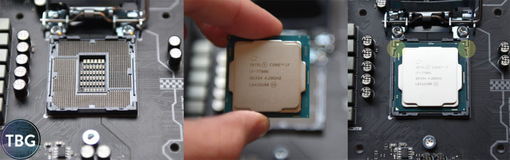
All right, let’s move right into the installation of the CPU. We’ve put together a compilation of photos to help guide you through each step. Many of our readers have asked us to post “build videos” to help them through the process, but from our point of view, videos really can’t provide the level of detail required to truly teach you how each component goes together.
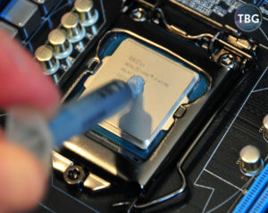
A lot of first-time builders are worried that they’ll break something during the build process. Based on our experience, as well as our interactions with hundreds of readers over the years, we believe there’s just one step that can cause problems: bending motherboard pins. In the photo below, you’ll see the uncovered CPU socket, with over one thousand tiny metal pins. If even one of these is displaced, the system may not run. Unfortunately, during our many, many rebuilds, we have in fact damaged these pins, and yes, it will cause a system failure. So please, handle the CPU as you see in the photo below, and carefully place the CPU in the socket straight down, making sure the two tabs on either side of the socket line up with the two notches in the CPU. Under no circumstances should you slide the CPU in from the side of the socket.
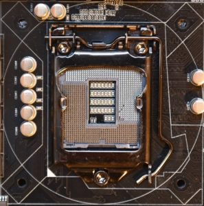
Not to scare you or anything, but we thought it appropriate to provide one more warning – to the left is a photo of what bent motherboard pins look like. These pins were damaged during a routine CPU change in the course of a product review. One little slip and our CPU dropped from our fingers and caught a few pins, displacing them enough that we simply couldn’t pull them back into position. This motherboard was unfortunately toast… although amazingly enough we have in the past been able to resuscitate motherboards we’ve damaged under similar circumstances using nothing more than a tweezers, reasonably-good eyesight, and a steady hand!
OK, that’s truly the hardest part, but the next steps are the “scariest.” Pay close attention to the photos below and you’ll be OK! First you slip the bracket under the securing bolt (you don’t actually unscrew the bolt), and then you lower the locking arm and slide it under the metal bracket. It will feel like you’re absolutely crushing the life out of your CPU, but if you placed it in the socket correctly, everything will be just fine! Note that the black plastic socket protector will automatically pop off when the CPU is locked in.
Ta-da, your CPU is in place, and you’re ready to move on!
Installing the CPU Cooler
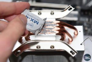
The next step is to install the CPU cooler. Depending on the model you choose, this could take a lot of dexterity, and potentially seem like it requires three hands to accomplish. We selected a very user-friendly cooler, the Arctic Freezer i32, which has a simple bracket that adheres to the back of the motherboard (a nice trick!), and a straightforward retention system. This cooler even comes with very high-quality thermal interface material (TIM), Arctic’s own MX-4. The only issue we have with it is that it ships in a plastic packet, which makes it a bit harder to apply than the syringe that you’d get if you bought a retail package of MX-4. So please excuse the somewhat messy application here – the CPU won’t mind!
By the way, important note: on coolers with exposed heatpipes, you need to apply the TIM across the bottom of each pipe, rather than a pea-sized amount directly on the CPU heat spreader. That’s because the gaps between the exposed heatpipes will stop the TIM from flowing as you secure the cooler to the CPU. We’ve included a photo here of the pea-sized application in case you’re using a cooler with a flat heat transfer plate.
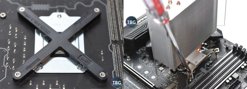
OK, the next step is to attach the rear retaining bracket, and then mount the cooler. Generally, the bigger the cooler, the harder this is to do, although some small, cheap coolers are also difficult to install, due to inferior mounting mechanisms. The Freezer i32 is one of the best coolers out there in terms of ease of use, so as you can see, we just insert the bracket, flip the motherboard over, and secure the cooler, affixing the screws in alternating fashion (half-turn, alternate, half-turn, alternate, and so on). The idea is to get even mounting pressure all the way around the CPU.
By the way, while we don’t have this pictured, you’ll need to attach the CPU cooler’s fan to the heatsink, and then plug in its 4-pin power cable to the CPU_FAN header on your motherboard. We figured you didn’t need photos to remind you that yes, a high-end CPU needs a working fan!
Installing the RAM
Installing RAM should be one of the easiest steps in building a PC, especially given that most PC users have probably had the opportunity to install, or at least look at, RAM in pre-built systems. The trick is that modern DDR4 RAM has a very tight interface, perhaps to improve signaling speed. In any event, DDR4 sticks have tripped us up more than once, and we’ve had dozens and dozens of readers comes to us since DDR4 was first released in 2015 to say their systems are broken and won’t boot, only for us to point out that the RAM has to be fully locked in for the system to run. Yes, this in fact means that even if you have one stick in properly, a second stick improperly inserted will cause a system to fail to boot. In other words, you’ve got to get this step perfect!
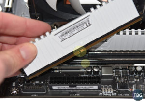
The first thing you need to do is make sure you’re inserting the RAM in the right direction. Oddly, this often means inserting it with the decorative label facing in, where you can’t see it, and the boring specification label facing out. This is how our Corsair RAM needs to be inserted in our MSI motherboard. You can determine the proper orientation by looking for the tab in the slot and the matching notch in the RAM module. Once you have these two items lined up, you press straight down until both locking tabs fully engage. Note that some motherboards use a single locking tab on the top of the slot, but regardless of the mechanism, if it’s not fully locked in, the RAM has not been fully inserted. Please give the RAM an extra push with your motherboard on a flat surface to make sure that the RAM is really, truly in all the way. Not to beat a dead horse here, but this is the #1 cause of PC boot failures, not “DOA motherboards,” which you’ll read all about in misguided user reviews and forum posts!
Note that the proper order to use RAM slots is to start with the second slot away from the CPU if you have one stick, the second and fourth if you have two sticks, and obviously all four if you have four sticks. We strongly encourage you, however, not to run a single stick (or three sticks, for that matter), as it means you’ll lose dual-channel operation, which provides a 3-5% performance boost in most applications.
Installing the SSDs
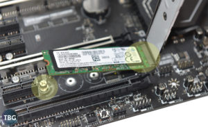
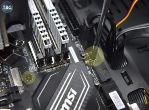
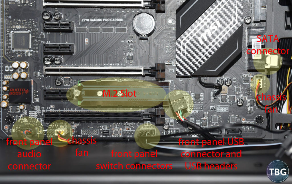
OK, we’re almost done prepping our motherboard, but there’s one more step: inserting the M.2 solid-state drive. This slots into the motherboard a bit like a stick of RAM; in some ways it’s actually easier, but one element of the installation makes it a bit harder. The slot itself is spring-loaded, meaning it’s impossible to insert the SSD in and not have it make contact with the slot. It’s really very simple. The tricky part is that you need to screw it down, and this requires two steps. First of all, you must confirm that the mounting post is in the right position for your SSD. Most modern M.2 SSDs are 80mm long, but motherboards may ship with the mounting post in the 60mm or 110mm position. So you’ll need to pull out that trusty jeweler’s-type screwdriver we mentioned earlier and move it over.
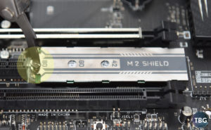
Then you need to hold down the M.2 drive against it’s spring-loaded retention mechanism and secure it to the post with a teeny, tiny screw. Yes, for some reason, every motherboard manufacturer has decided that M.2 drives should be secured with screws that cannot be affixed with standard #2 Philips-head screwdrivers. We’ve tested boards from Asus, Gigabyte, and ASRock, along with the MSI board shown here, and they all have these tiny screws that are hard to hold onto and easy to lose, unfortunately. Just be patient, and preferably, install the SSD before you have the motherboard in the case. Dropping the screw when the board is flat on the ground or a table is a whole lot better than dropping it into your case. By the way, all of this is well worth the effort, given that once the M.2 drive is in, you’re done – no cables required!
The next step is to mount your 2.5″ or 3.5″ drive. We have stopped using 3.5″ drives in TBG’s bench systems all together, so we’re not demonstrating how to install one here, but if you have one, you probably know how to install it using the case’s standard 3.5″ drive trays. Nothing complicated there. The 2.5″ drive sleds incorporated into all modern cases might be a bit trickier to use, as you typically have to mount them vertically and they aren’t always tool-less, but ultimately, it’s still pretty simple. Note that the screws you’ll need to affix the drive come with the case. Please, please do not buy the aftermarket 2.5″-to-3.5″ driver bay converters that too many of our readers still get tricked into buying when they see these pop up online. You don’t need them, and you haven’t need them for at least five years!!!
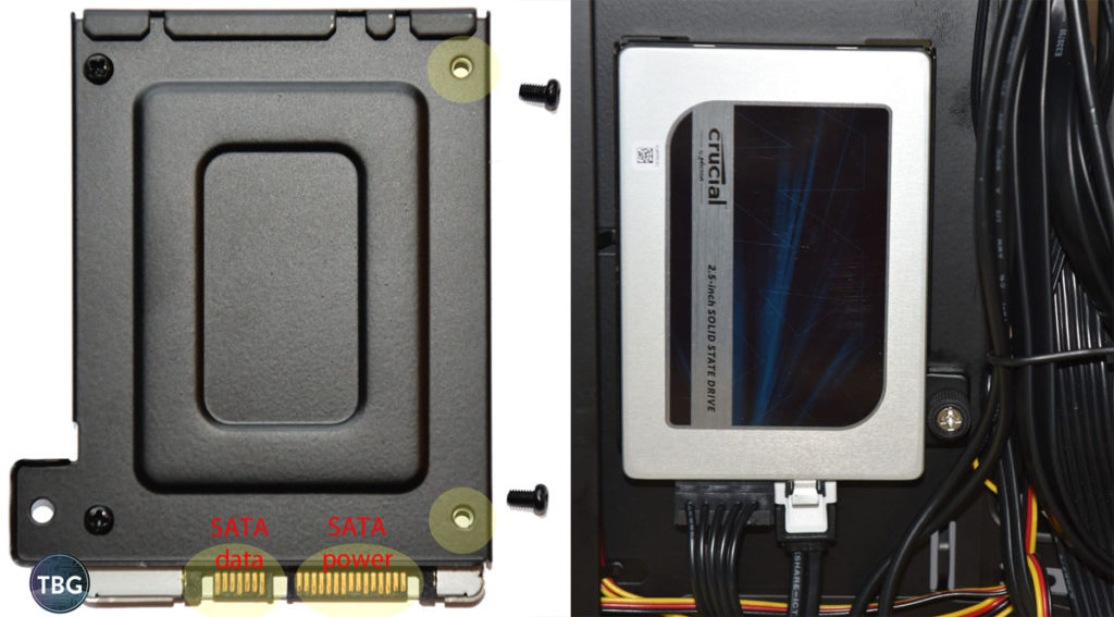
As you can see above, we’ve highlighted the screw holes you’ll need to use to affix the drive to the tray, as well as the two connectors you’ll be using to provide power and data for the drive. The sled attaches to the inside of the case, behind the main compartment, and our case included two such sleds, although the number of sleds provided will vary depending on the case you use. Note that because we’re using a modular power supply, we can actually attach our SATA power cable to the drive before the power supply is even in the case, and we’ve routed the SATA data cable through to the main chamber of the case, in preparation for installation of the motherboard.
OK, now we’re ready to get the guts of the system installed into our case. Next we’ll see how it all comes together.
Installing the Power Supply
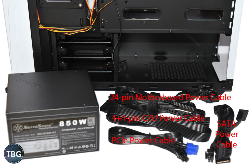
Hopefully, if you’re building a high-end PC today, you’re using a fully-modular power supply. We wouldn’t recommend anything of the non-modular or semi-modular variety if you’re spending more than $75 on a PSU (which you should when building a high-end PC, by the way). In the accompanying photo, we’ve labeled the key cables that just about any build will require, so that you can pull them out of the PSU parts box. Note that systems using only M.2 drives will not require any SATA power cables, which provides for a very clean build. We’ve included both M.2 and 2.5″ drives in our build for illustration purposes. Another thing to note: depending on the video card you use, you may need to run dual PCIe power cables. This is vastly preferable to using the splitter that may come in the box with your video card. Our GeForce GTX 1070 card only required a single 8-pin power cable, so we’ve only pictured one in the photo here.
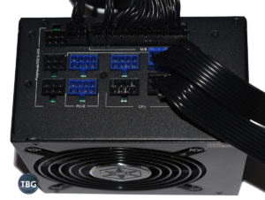
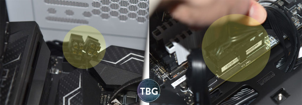
If you’re using a case with a PSU shroud, you’ll definitely want to connect all the necessary cables before inserting the PSU into the case. That’s because reaching under the shroud to install modular cables is very challenging due to the limited working space. Make sure to fully insert each of these cables until the locking tab clicks in. Otherwise, you may find your system unable to boot once it’s all come together, and you’ll be left scratching your head as to what’s wrong. Every build will require at least two cables: the 24-pin motherboard power cable, and the 4+4-pin CPU power cable. This CPU cable is split at the motherboard side because some basic motherboards only require a 4-pin connection, but all high-end boards will require that you join the two ends together to form a single 8-pin connector. As we mentioned, we also have a SATA power cable for our 2.5″ solid-state drive, and a PCIe power cable for our GTX 1070 graphics card.
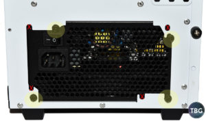
Now here’s a step you might not see covered elsewhere, but it’s an important one: screwing in the power supply. Unfortunately, we actually had a reader destroy a power supply by picking up a long screw (rather than the short screw that came with the power supply), and affixing the screw directly into a vent hole, damaging a capacitor inside the power supply and rendering the power supply inoperable. The power supply is designed to be inserted with the fan either up or down, depending on the internal layout of your case, and that’s why it appears there are eight screw holes you can use to affix your power supply. In fact, there are only four you can use, and you should make doubly-sure you are using the right ones before you go screwing into a vent hole. Truth be told, we’ve made this mistake before, but luckily didn’t damage any internal PSU components! We’ve highlighted the holes to be used to mount a PSU with the fan pointed down (as you’ll do with most modern cases), and we’ve “X’d out” the locations that look like screw holes, but are in fact PSU vent holes that you want to avoid screwing into.
All right, as seen here, our power supply is now fully installed, and we’ve routed the cables so as to get them ready for motherboard installation. Note the 4+4-pin CPU cable is routed up to the rear corner of the case, while the 24-pin and PCIe power cables are routed to the center of the case. To keep things simple in this photo, we’ve removed the SSD.
Installing the Motherboard
Now it’s time to drop in your motherboard, which will turn this shell of a PC into the real thing! Note that there are two steps you need to take before inserting the motherboard. First, slot the I/O panel into the back of the case. Hopefully, you’re lucky enough to have a padded I/O cover, which higher-end boards like our sample MSI Z270 Gaming Pro Carbon come with. Otherwise you’ll be stuck with a punched-metal panel that’s a lot harder to install, and has all sorts of hanging bits of metal that can get in the way of ports. They never fail to block at least one USB or HDMI port, in our experience (and to our chagrin!).
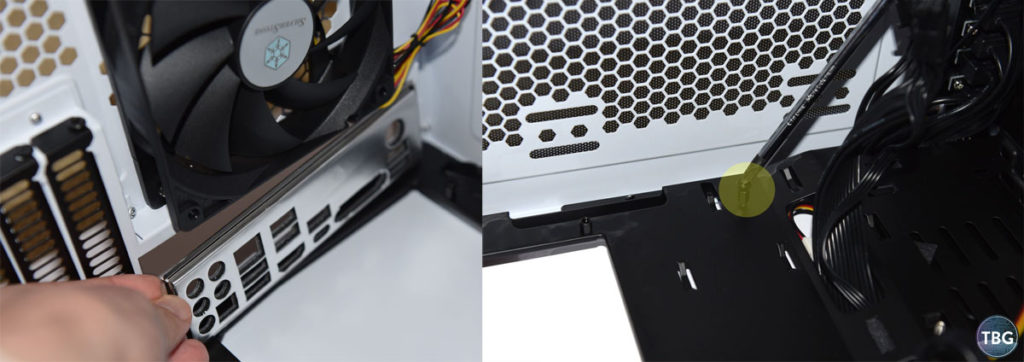
The other step you need to take before dropping the board in is to confirm that the correct motherboard standoffs are installed in the case. Many cases, including the SilverStone model we used, only include six pre-installed standoffs. That’s because some budget motherboards are narrower than the standard ATX spec and don’t require the full complement of nine standoffs. We find that the easiest way to screw these posts in is actually to insert a screw into them, and affix the whole thing together, and then back the screw out once the post is in. You might need a pliers to accomplish this by the way. In the photo above, you can see that we’re installing a new standoff in the top-right corner of the motherboard tray. With that out of the way, we’ll drop the motherboard in and secure it to the standoffs. In the photo here, we’ve highlighted a screw in the middle of the board, as well as a screw on the right side of the board that’s being affixed. Remember how on the first page of this guide, we recommended a magnetic-tip screwdriver? This is the step where you’re going to be very thankful you have one. It makes reaching the screw holes at the top of the board a whole lot easier!
The next step is the one that will require some dexterity: attaching all the power and data cables to the board. This includes the 24-pin and 4+4-pin power cables that come from the power supply, the SATA data cable for any 2.5″ or 3.5″ data drives you’re using, fan cables, as well as the assortment of cables that come from the front of the case (USB, audio, and power buttons and LEDs). In the photo above, we’ve highlighted all the smaller data cables you’ll need to attach (with the exception of the USB 3.0 cable, which is up near the 24-pin power connector). Note that every motherboard manufacturer has a slightly different approach to how users should attach the front panel connectors. As it happens, MSI chooses to make it as difficult as possible, as there is no extra key insert that you can attach your cables to outside of the case, nor is there a silkscreened legend on the motherboard itself. You actually need to read the manual, shockingly. Our favorite attachment system is found in Gigabyte boards, followed closely by Asus and AsRock boards. In the photo below, we’ve highlighted the two power cables that must be connected for the system to boot. You’ll want to make extra certain these are inserted all the way, because a half-inserted cable will not provide proper power.
Installing the Video Card
Believe it or not, we’re almost done. Now comes the fun part: installing the beast of a video card that will turn this docile system into a true gaming powerhouse! Everything we’ve done so far would be relevant for a simple home office PC, by the way, and if that’s what you’re building, you can stop right here and load up your OS. But if you’re actually building a gaming system, read on!
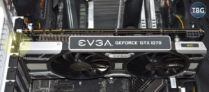
Installing the video card isn’t too hard, but you’ll want to make sure you drop it down straight into the PCIe slot to avoid any potential damage to the motherboard. It helps to have the case laying on its side here, so you can easily see what you’re doing and have gravity help you, rather than hinder you. Then you’ll affix the two PCIe slot screws that are pre-installed in the case (and which you removed when you pulled the slot covers out – you did do that, right?!?).
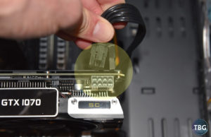
Now here’s a step a lot of builders forget about: connecting the PCIe power cable to the video card. Yes, you do need this connected for your video card to work, and yes, you do need all of the pins filled. So if you have a 6-pin cable in your hand, but your video card requires an 8-pin cable, you’ll need to dig through the cables that came with your power supply and find the correct one. The 6-pin standard is slowly giving way to the 8-pin standard, so what most current power supplies use is a split 6+2-pin cable that can be used for either arrangement. You’ll see that highlighted in the accompanying photo here. You’ll need to fit the two sides of this connector together and then insert it into the video card if you do indeed need 8 pins, as we do for the GTX 1070 we used.
Hey, guess what? The system’s ready to run! In the photo below, this PC is fully cabled up, and all we need to do is plug our power supply into a power outlet and press the power button. It will start up first time, right?!?
Well, nine times out of ten, there’ll be some minor snag a first-time (or 100th-time) builder will hit that keeps this system from running, so make sure to double-check all your power cables, your RAM, and your front panel connectors before pressing that power button to avoid any nasty surprises!
Overclocking
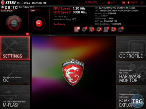
Assuming your system boots (big assumption!) and you’re able to install your OS, you might want to try your hand at overclocking. We’ve assembled a series of UEFI screenshots (click on any to magnify) setting forth what you should be looking for to overclock a Kaby Lake-based processor (e.g., the Core i5-7600K or Core i7-7700K). To access the UEFI, tap the delete key during the boot sequence. You’ll be greeted by a colorful screen like the one you see here, which is for the MSI Z270 Gaming Pro Carbon board we used. The first thing you’ll want to do is enable your RAM’s XMP profile, which in this UEFI is done simply by clicking a button in the upper-left. For other UEFI’s you may have to hunt around a bit for it in the menu. Note that we strongly, and we do mean strongly, discourage you from attempting to manually overclock RAM beyond the XMP settings. In most cases, this will fail instantly, and in nearly every other case, it will appear to work but will cause random system bluescreens. In other words, it’s not worth it!
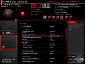
The next step is to enter the CPU overclocking menu. You’ll want to engage the manual overclocking mode, called “Expert” here, but may be called “advanced” or “manual” in other UEFIs. What you’ll see is that we’ve dialed in a 50x multiplier (which translates to 5GHz under load). Note that with any manual overclocking, the Turbo function is shut off, so the instant you enter in a custom multiplier, all the various Turbo levels are disabled. A Core i7-7700K operates at 4.4GHz under a quad-core load at stock settings due to its Turbo function, which means that 5GHz, as impressive as it sounds, is actually just a 14% overclock. Furthermore, to prevent overheating and to maintain the utmost stability, we entered in a -4 offset for AVX loads, which will reduce the operating clock speed to 4.6GHz in AVX tasks, including some benchmarking and stress-testing applications. As it turns out, our CPU was capable of sustaining 5GHz in AVX loads, but it pushed very high voltages and temperatures, so we’re going to recommend that all but the most expert of tweakers use that helpful AVX offset.
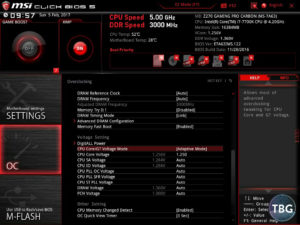
Next you have to provide additional voltage. In our testing, the motherboard would automatically increase voltage to provide a stable overclock at 5GHz, but the voltage was actually too high, leading to extremely-high temperatures. Therefore, we recommend that you select “adaptive” mode (or the new adaptive + offset mode that’s been added for Z270-based motherboards), and manually enter a voltage level. We chose 1.25V, which is pretty low for 5GHz, but it was stable in our testing. It actually translated to about 1.26V in Windows, as you’ll see momentarily. Choosing adaptive rather than “fixed” or “override” will allow the voltage to back off at idle, which is great for reducing power usage and excess heat.
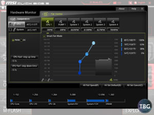
Before we save our UEFI overclock and restart the system, we want to enter the UEFI’s Hardware Monitor to dial in some custom fan profiles. By default, motherboards will often run case and CPU fans close to full speed, but an expert builder should customize these to allow for low fan speeds at low temperatures, and maximum fan speeds under extreme stress. Our unique Arctic Freezer i32 CPU Cooler can actually properly run at zero RPM (most fans may buzz or throw a UEFI error if set to 0). We take advantage of that feature here by having the fan only start spinning at 55 °C. By 85 °C, it will be at 100%. You can go through each one of your case fans and do something similar, but we suggest you start at 40% (or alternatively around 600RPM) to avoid the fan buzzing due to inadequate voltage. Many case fans will not operate properly below this level.
OK, once we save our settings and restart, we’ll hopefully arrive at the Windows desktop – if we don’t, we may have to tweak our overclock and voltage settings. Luckily, we didn’t run into any trouble, so can go ahead and run a few benchmarks to see how this overclock is doing:
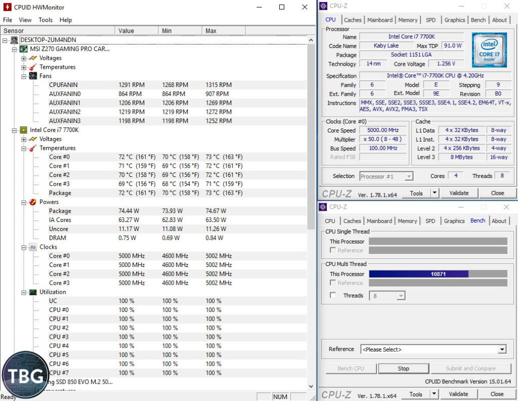
Good news! Under the moderate load presented by the stress test built into the handy utility CPU-z, our system is humming along just fine at 5GHz. According to HWMonitor (another great utility by the same folks who created CPU-z), the CPU temperature doesn’t exceed 73 °C, thanks in part to the moderate 1.256V running through the processor. We consider CPU-z a very good approximation of the load that typical applications will generate, including games. Unless you’re doing serious video transcoding or other demanding work, you won’t hit higher temperatures. But let’s see how things go when we throw an AVX load at the system courtesy of Intel Burn Test.
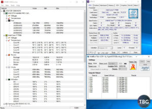
Ah, nice and toasty! The CPU hit 83 °C, despite the fact that the CPU was operating at 4.6GHz, thanks to that useful -4 (i.e., -400 MHz) offset we selected in the UEFI. Here voltage exceeded 1.26V. Note that this is still in the safe zone, but the compact CPU cooler we used (the Arctic Freezer i32) is probably the minimum cooler you’d want to go with for serious Kaby Lake overclocking. Because the case we used only had about 160mm of clearance for CPU coolers (158mm according to the specs, but we measured a bit more than that), big 140mm-based tower coolers were out of the question. They’d stick right out the side of the case. This is something builders really have to be careful about when they try to mix and match coolers and cases. We always triple-check compatibility in our Do-it-Yourself PC Buyer’s Guides, so that’s a good resource to consult if you’re looking for a matching setup.
In terms of GPU overclocking, things are actually quite a bit simpler, for better or for worse. As it happens, with the current generation of Pascal-based GPUs, there’s really very little to overclocking, both in terms of effort and reward. Every Pascal-based GPU we’ve tested (and we’ve tested over half a dozen) will hit between 2000MHz and 2100MHz, which translates to a 8-12% overclock. Just download MSI Afterburner (our favorite free utility by far) and start with a +150MHz offset above reference, and see how far you can push it.
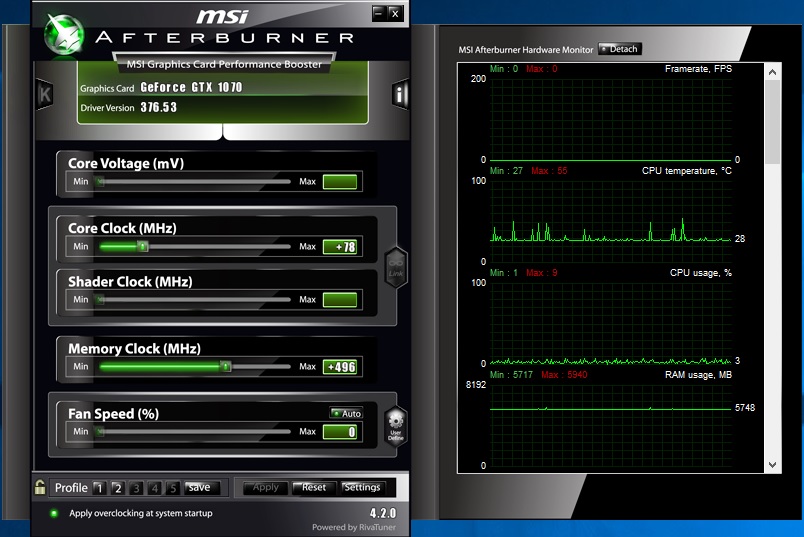
Because our EVGA GeForce GTX 1070 SC 8GB card came pre-overclocked from the factory by about 90MHz, we added an additional 78MHz in MSI Afterburner, as shown in the screenshot here, to arrive at a total overclock of 167MHz. Depending on how you calculate it (versus base clocks, published boost, or actual in-game clockrates), this is about an 11% overclock. Most cards will start crashing before they get to +200MHz. In terms of VRAM overclocking, you can typically get between a +250MHz and a +500MHz offset (which due to the effect of double-data rate RAM translates to an overclock of 500MHz to 1000MHz). Our card was stable with a +496MHz memory offset, and we didn’t push higher.
Final Thoughts
 There’s really nothing more rewarding than using your own two hands, a little patience, and a little ingenuity to build yourself an ultra-capable PC. We know that the thousands of readers around the world who have followed our guides over the past four years would probably agree, which is why we keep coming back and publishing guides like this one month after month and year after year!
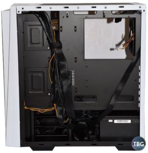
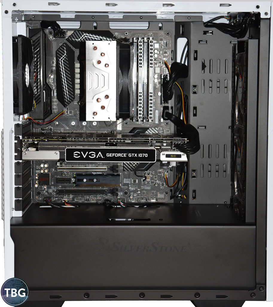
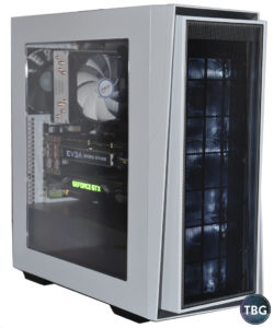
And the great thing is you can choose your own price level, form factor, and combination of capabilities to fit your needs and your needs alone. Just because someone else has a hulking tower for a PC doesn’t mean you have to! We specifically chose an ultra-compact ATX case because we think this form factor is kind of cool, even if it is just a bit limiting in terms of what can be crammed inside. By the way, all you eagle-eyed readers will notice that we made one final “adjustment” to our build, just for fun. Take a look inside our system’s windowed side panel and check out what we managed to add to our build. Yes, it really works, no thermal issues whatsoever thanks to the excellent SilverStone RL06-Pro case!
We hope you’ve found this guide useful… perhaps it will even inspire you to build your next PC! As always, to see our latest recommendations on component picks in every price range, check out our Do-It-Yourself Buyer’s Guides, updated on a monthly basis to keep you up to speed on all the latest developments.